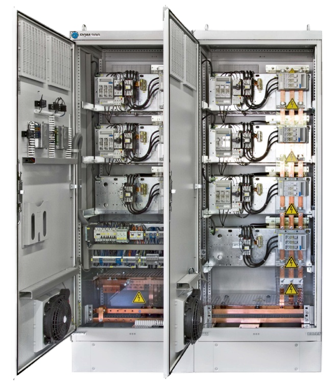
Baron reactor based Passive Harmonic Filters Systems are suitable for suppressing harmonics generated by destructive loads.
High harmonics can cause: Increased System Losses, High Frequency Currents, Malfunction of relays and circuit breakers, passive har filterFuse Operation, Capacitor failures, Motor and Transformer Overheating.
Maintains healthy power factor where V-THD & I-THD level is above IEEE / IEC Guidelines.
Classification and Selection
The Harmonic Filter Systems are classified depending on the tuning frequency of the filter reactor & capacitor circuit and the selection of harmonic filter type depends on the level & order of harmonics present in the distribution network.
Salient Features
- Microprocessor based power factor controller with special features, four quadrant measurements
- Accuracy of +0.8% for Reactive Power, + 0.5% for Current, 6 or 12 steps to operate Capacitor-Reactor Circuits.
- Precise and quick relay controls
- Continuous monitoring of defective capacitor stages
- Counting, Storing and Display of number of switching operation
- Alarm for excess operation than programmed limits.
- Dual control curve characteristics: to avoid over compensation under light loads and to avoid inductive reactive power under regenerative conditions.
- Monitoring of harmonic levels continuously with alarm and safety trip facility.
- Zero voltage & Zero current tripping with alarm signals.
- Manual/Automatic operation with ability to switch each individual capacitor

Parameters Measured and Displayed
- Voltage
- Current
- Reactive Power
- Power Factor
- Frequency
- Harmonics
System Protection by Incoming Moulded Case Circuit Breaker selected with tripping characteristics for the Individual Capacitor Reactor Circuit as well as multi bank parallel switching characteristics
Feeder Protection by MCB having tuned tripping characteristics to ensure avoidance of any inadvertent tripping by inrush current of the capacitors
Filter Duty Contactors enables the switching of different stages of the Filter System for varying loads.
Capacitor Switching Thyristor Module is used when the requirement is of high speed reactive Power Compensation for highly fluctuating loads.
Capacitors of Cylindrical, Dry Type, and Segmented Metallised Polypropylene Construction with patented Spring loaded Terminals and Overpressure Disconnector safety features present in the Distribution Network.
Super Heavy Duty Capacitors
Over Current Withstand Capability – Min. 1.8 times IN at rated Voltage permanently & Min. 250 times IN during short peak currents
Wattage Loss – 0.2 Watt/KVAR at Capacitor Coils and 0.5 Watts/KVAR at Terminals including Discharge Resistors
Temperature Withstand Capability – –40°C to + 60°C.
Voltage – 480V/525V
Application – Tuned/ Detuned.
Heavy Duty Capacitors
Over Current Withstand Capability – Min. 1.5 times IN at rated Voltage permanently &Min. 200 times IN during short peak currents
Wattage Loss – 0.2 Watt/KVAR at Capacitor Coils and 0.5 Watts/KVAR at Terminals including Discharge Resistors
Temperature Withstand Capability – –25°C to + 55°C
Voltage – 480V/525V
Application – Tuned/ Detuned.
Harmonic Filter Reactors with low loss Iron Core Design
Design – Iron Core Design
Ambient Temperature – 60º C, maximum ambient temperature
Insulation Class – F
Linearity – 1.75 x IN at reduction of the Inductivity
IN – Current from QLC without harmonic load
ITH = 1.22 x IN – Max. Permissible effective value of the current considering 10% over voltage and the permissible harmonic currents
Alarms
The Alarm Signal is initiated for abnormalities in the System. The alarm can be Accepted & Re-set by pressing of Manual / Reset Push button.
Alarms Indicated
- Power factor Alarm – “U=0” Alarm
- Harmonic Alarm – “C=0” Alarm
- Over-current Alarm – “I=0” Alarm
Benefits
No failures due to Harmonic Overloading – Lowered heating in induction motors and improved performance by reduction of harmonic torques
Reduced losses in the distribution system and motor loads – Shielding of sensitive electronic control equipment
Avoidance of harmful resonance/amplification of harmonics – Avoidance of failure of Power Factor Correction unchoked capacitors due to excessive harmonic overheating
